SECTION 4
DATA MODEL
4.1 INTRODUCTION TO DATA MODELS
The purpose of this guide is to provide a context for reading and understanding IDEF1X semantic data models. It is not intended to be an instructional manual in the techniques of building such models; rather, it is intended to specify the basic components of a semantic data model and their interpretation.
IDEF1X has proven to be a useful and powerful tool for modeling a conceptual schema. IDEF1X models define data in a fully normalized structure, which allows an initial model to be extended without altering the initial set of entities, relationships, and attributes. An IDEF1X model of a conceptual schema can be easily subsetted and formally mapped through relational algebra to both external and internal schema. The U.S. Air Force IISS and IDS projects have successfully demonstrated the use of IDEF1X mo
dels and its formal mappings to manage data stored under the control of each of the classical database models (hierarchical, network, and relational). IDEF1X models are also being used to automatically generate database designs and data integrity control logic.
IDEF1X semantic constructs are formally defined mathematically (using both set theory and first order logic) based on extensions to the relational theory work of Dr. Ted Codd and the entity-relationship modeling work of Dr. Peter Chen. IDEF1X also incorporates ideas such as property inheritance and semantic constructs for generalization, aggregation, classification, and association developed as a result of AI research on semantic networks. IDEF1X provides a full set of semantic modeling capabilities wh
ile maintaining the "economy of concepts" associated with basic E-R modeling.
4.1.1 Components of an IDEF1X Model
The IDEF1X modeling techniques include a set of modeling semantics, graphic syntax for representing the semantics, rules for modeling, modeling procedures, and documentation formats.
The result of applying the IDEF1X modeling technique is a specification of data meanings and rules typically represented by the following:
- A set of graphic diagrams representing real or abstract objects, their characteristics or attributes, and their relationship to one another. Data model diagrams are refined into three different levels of detail:
- Entity-relationship, the least detailed level.
- Key-based, the next level of detail.
- Fully attributed, the most detailed data model level.
- A glossary that defines the entities and attributes used in the diagrams.
- Business rules or entity relationships that are written descriptions of the manner in which data relates to other data. They describe the data constraints that exist in the environment.
4.1.2 Entity Semantics
An "entity" represents a set of real or abstract things (people, objects, places, events, states, ideas, pairs of things, etc.) which have common attributes or characteristics. An individual member of the set is referred to as an "entity instance." A real world object or thing may be represented by more than one entity within a data model. For example, John Doe may be an instance of both the entity EMPLOYEE and BUYER. Furthermore, an entity instance may represent a combination of real world objects. Fo
r example, John and Mary Doe could be an instance of the entity MARRIED-COUPLE.
In key-based and fully attributed models, a distinction is made between two types of entities. An entity is "identifier-independent" or simply "independent" if each instance of the entity can be uniquely identified without determining its relationship to another entity. An entity is "identifier-dependent" or simply "dependent" if the unique identification of an instance of the entity depends upon its relationship to another entity.
An entity is represented as a box as shown in Figure 4-1. If the entity is identifier-dependent then the corners of the box are rounded. Each entity is assigned a unique name and positive integer which are separated by a slash, "/", and placed above the box. The entity name is a noun phrase (a noun with optional adjectives and prepositions) that describe the set of things the entity represents. 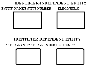 The noun phrase is singular, not plural. Abbreviations and acronyms are permitted; however, the entity name must be meaningful and consistent throughout the model. A formal definition of the entity and a list of synonyms or aliases must be defined in the model glossary. Although an entity may be drawn in any number of diagrams, it only appears once within a given diagram.
Figure 4-1 Entity Syntax
4.1.3 Non-Specific Relationship Semantics
In a key-based and fully attributed IDEF1X model, all associations between entities must be expressed as specific binary relationships. However, in the initial development of a model, it is often helpful to identify "non-specific relationship" between two entities. These non-specific relationships are refined in later development phases of the model.
A non-specific relationship, also referred to as a "many to many relationship", is an association between two entities in which each instance of the first entity is associated with zero, one, or many instances of the second entity and each instance of the second entity is associated with zero, one, or many instances of the first entity. For
example, if an employee can be assigned to many projects and a project can have many employees assigned, then the connection between the entities EMPLOYEE and PROJECT can be expressed as a non-specific relationship. This non-specific relationship can be replaced with specific relationships later on in the model development by introducing a third entity, such as PROJECT-ASSIGNMENT, which is a common child entity in specific connection relationships with the EMPLOYEE and PROJECT entities. The new relationsh
ips would specify that an employee has zero, one, or more project assignments and that a project has zero, one or more project assignments. Each project assignment is for exactly one employee and exactly one project. Entities introduced to resolve non-specific relationships are sometimes called "intersection" or "associative" entities.
A non-specific relationship is depicted as a line drawn between the two associated entities with a dot at each end of the line. See Figure 4-2. A non-specific relationship is named in both directions. The relationship names are expressed as a verb phrase (a verb with optional adverbs and prepositions) placed beside the relationship line and separated by a slash, "/".

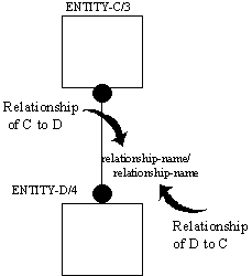
Figure 4-2 Non-Specific Relationship Syntax
4.1.4 Connection Relationship Semantics
A "specific connection relationship" or simply "connection relationship" (also referred to as a "parent-child or existence-dependency relationship") is an association or connection between entities in which each instance of one entity, referred to as the parent entity, is associated with zero, one, or more instances of the second entity, referred to as the child entity, and each instance of the child entity is associated with exactly one instance of the parent entity. That is, an instance of the child enti
ty can only exist if an associated instance of the parent entity exists. For example, a specific connection relationship would exist between the entities BUYER and PURCHASE-ORDER, if a buyer issues zero, one, or more purchase orders and each purchase order must be issued by a single buyer.
The connection relationship may be further defined by specifying the cardinality of the relationship. That is, the specification of how many child entity instances may exist for each parent instance. Within IDEF1X, the following relationship cardinalities can be expressed:
- Each parent entity instance may have zero, one or more associated child entity instances.
- Each parent entity instance must have at least one or more associated child entity instances.
- Each parent entity instance can have none or at most one associated child instance.
- Each parent entity instance is associated with some exact number of child entity instances.
If an instance of the child entity is identified by its association with the parent entity, then the relationship is referred to as an "identifying relationship". For example, if one or more tasks are associated with each project and tasks are only uniquely identified within a project, then an identifying relationship would exist between the entities PROJECT and TASK. That is, the associated project must be known in order to uniquely identify one task from all other tasks. (Also see Foreign Keys Semantics
)
If every instance of the child entity can be uniquely identified without knowing the associated instance of the parent entity then the relationship is referred to as a "non-identifying relationship". For example, although an existence-dependency relationship may exist between the entities BUYER and PURCHASE-ORDER, purchase orders may be uniquely identified by a purchase order number without identifying the associated buyer.
Assertions that affect multiple relationships may also be defined. One type of assertion may specify a Boolean constraint between two or more relationships. For example, an "exclusive OR" constraint states that for a given parent entity instance if one type of child entity instance exists, then a second type of child entity instance will not exist. However, if both the parent and child entities refer to the same real world thing, then a potential categorization relationship exists (See Categorization R
elationship Semantics).
Another type of constraint is a "path assertion," which constrains the specific instances of parent and child entities when two entities can be related either directly or indirectly through two different sequences of relationships. For example, the entity DEPARTMENT may have two child entities, EMPLOYEE and PROJECT. If the entities EMPLOYEE and PROJECT have a common child entity called PROJECT-ASSIGNMENT, then PROJECT-ASSIGNMENT is indirectly related to DEPARTMENT via two different relationship paths.
A path assertion might state that "employees may only be assigned to projects which belong to the same department for which they work".
A specific connection relationship is depicted as a line drawn between the parent entity and the child entity with a dot at the child end of the line. The default child cardinality is zero, one, or many. A "P" (for positive) is placed beside the dot to indicate a cardinality of one or more. A "Z" is placed beside the dot to indicate a cardinality of zero or one. If the cardinality is an exact number, a positive integer number is placed beside the dot. See Figure 4-3.
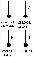
Figure 4-3 Relationship Cardinality Syntax
A solid line depicts an identifying relationship between the parent and child entities. See Figure 4-4. If an identifying relationship exists the child entity is always an identifier-dependent entity, represented by a rounded corner box, and the primary key attributes of the parent entity are also inherited primary key attributes of the child entity. (Also see Foreign Keys Semantics).
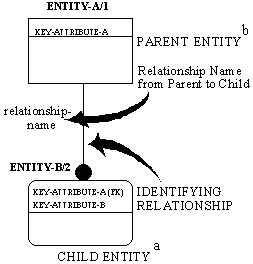
Figure 4-4 Identifying Relationship Syntax
- The Child Entity in an Identifying Relationship is always an Identifier-Dependent Entity.
- The Parent Entity in an Identifying Relationship may be an Identifier-Independent entity (as shown) or an Identifier-Dependent Entity depending upon other relationship.
The parent entity in an identifying relationship will be identifier-independent unless the parent entity is also the child entity in some other identifying relationship, in which case both the parent and child entity would be identifier-dependent. An entity may have any number of relationships with other entities. However, if the entity is a child entity in any identifying relationship, it is always shown as a identifier-dependent entity with rounded comers, regardless of its role in the other relationshi
ps.
A dashed line depicts a non-identifying relationship between the parent and child entities. See Figure 4-5. Both parent and child entities will be identifier-independent entities in a non-identifying relationship unless either or both are child entities in some other relationship which is an identifying relationship.
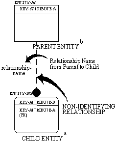
Figure 4-5 Non-Identifying Relationship Syntax
- The Child Entity in a non-identifying relationship will be an Identifier-Independent Entity unless the entity is also a Child Entity in some Identifying Relationship.
- The Parent Entity in a non-identifying relationship may be an identifier-independent Entity (As shown) or an Identifier-Dependent Entity depending upon other relationships.
A relationship is given a name, expressed as a verb phrase (a verb with optional adverbs and prepositions) placed beside the relationship line. The name of each relationship between the same two entities must be unique, but the relationship names need not be unique within the model. The relationship name is always expressed in the parent-to-child direction, such that a sentence can be formed by combining the parent entity name, relationship name, cardinality expression, and child entity name. For example
, the statement "A project consists of one or more tasks" could be derived from a relationship showing PROJECT as the parent entity, TASK as the child entity with a "P" cardinality symbol, and "CONSISTS OF" as the relationship name. Note that the relationship must still hold true when stated from the reverse direction, although the child-to-parent relationship is not named explicitly. From the previous example, it is inferred that "a task is part of exactly one project."
4.1.5 Categorization Relationship Semantics
Entities are used to represent the notion of "things about which we need information." Since some real world things are categories of other real world things, some entities must, in some sense, be categories of other entities. For example, suppose employees are something about which information is needed. Although there is some information needed about all employees, additional information may be needed about salaried employees that is different from the additional information needed about hourly employe
es. Therefore, the entities SALARIED-EMPLOYEES and HOURLY-EMPLOYEES are categories of the entity EMPLOYEE. In an IDEF1X model, they are related to one another through a categorization relationship.
A "complete categorization relationship" is a relationship between two or more entities, in which each instance of one entity, referred to as the generic entity, is associated with exactly one instance of one and only one of the other entities, referred to as category entities. Each instance of the generic entity and its associated instance of one of the category entities represents the same real-world thing and, therefore, have the same unique identifier. From the previous example, EMPLOYEE is the gen
eric entity and SALARIED-EMPLOYEE and HOURLY-EMPLOYEE are category entities.
Category entities for a generic entity are always mutually exclusive. That is, an instance of the generic entity can correspond to the instance of only one category entity. In the example, this implies that an employee cannot be both salaried and hourly. The IDEF1X syntax does allow, however, for an incomplete set of categories. If it is possible that an instance of the generic entity is not associated with any of the category entities, then the relationship is defined as an "incomplete categorizatio
n relationship."
An attribute value in the generic entity instance determines to which of the possible category entities it is related. This attribute is called the "discriminator" of the categorization relationship. In the previous example, the discriminator might be named EMPLOYEE-TYPE.
A categorization relationship is shown as a line extending from the generic entity to a circle which is underlined. Separate lines extend from the underlined circle to each of the category entities. Cardinality is not specified for the category entity since it is always zero or one. Category entities are also always identifier-dependent. See Figure 4-6. The generic entity is independent unless its identifier is inherited through some other relationship.
If the circle has a double underline, it indicates that the set of category entities is complete. A single line under the circle indicates an incomplete set of categories.
The name of the generic entity attribute used as the discriminator is written beside the circle. Although the relationship itself is not named explicitly, the generic entity to category entity relationship can be read as "can be." For example, an EMPLOYEE can be a SALARIED-EMPLOYEE. If the complete set of categories is referenced, the relationship may be read as "must be." For example, an EMPLOYEE must be a SALARIED-EMPLOYEE or an HOURLY-EMPLOYEE. The relationship is read as "is a/an" from the rever
se direction. For example, an HOURLY-EMPLOYEE is an EMPLOYEE.
The generic entity and each category entity must have the same key attributes. However, the role names may be used in the category entities. (Also, see Foreign Keys Semantics)
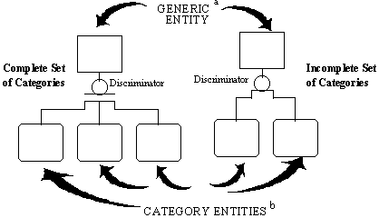
Figure 4-6 Categorization Relationship Syntax
- The Generic Entity may be an Identifier-Independent Entity (as shown) or an Identifier-Dependent Entity depending upon other relationships.
- Category Entities will always be Identifier-Dependent Entities.
4.1.6 Recursive Relationships
Recursive Relationships are a powerful, simple way of showing a very complex relationship. They can handle �n� levels of association. As you can see from the figure below, a simple change in cardinality can yield a hierarchical, network, or ordered list structure. The addition of date (and time) permit the structure to handle time varying structures. An entity may have more than one child recursive relationship. This permits multiple structures over time to be represented by the same entity relationshi
p combination.
| Network |
Hierachy |
Ordered List |
| Employee
| Employee
| Employee
|
 |
 |
 |
| Management Structure
| Management Structure
| Management Structure
|
 |
 |
 |
 |
 |
 |
Figure 4-7 Recursive Relationships
 Previous Section
|
Next Section
 The noun phrase is singular, not plural. Abbreviations and acronyms are permitted; however, the entity name must be meaningful and consistent throughout the model. A formal definition of the entity and a list of synonyms or aliases must be defined in the model glossary. Although an entity may be drawn in any number of diagrams, it only appears once within a given diagram.


 Previous Section
|
Next Section