SECTION 3
PROCESS MODELS
3.1 INTRODUCTION TO PROCESS MODELS
A Process Model is used to describe business activities and their relationships. Process Models are graphical representations of existing or planned processes and are excellent resources for understanding what functions are performed and how those functions interact. A primary purpose of a Process Model is to facilitate the discovery of information needs within the enterprise. A process represents an action or task that requires some amount of time to accomplish its objectives. Each process has a name t
hat is shown as a single strong action verb with a single explicit object that describes the process, action, or task that a process represents. A completed Process Model graphically depicts the specific steps, operations, and information needed to perform a process.
Process models are developed for several reasons. One of the most important uses of a Process Model is to define the scope of a project. The model may represent as broad or as narrow a viewpoint as is required and may be refined further and into more detail. If several viewpoints are desired, separate models may be developed for each.
Another use of the Process Model is for data discovery and validation. One of the primary functions of a Process Model is to show relationships between activities and the information that is used to perform each process. Data can be extracted from the model and can be used to specify transactions that may, in turn, eventually be used to automate the process. After these data elements are documented in the data model, the Process Model can be referenced for validation purposes.
Process Models are developed by persons with knowledge of the subject area under consideration. The team's knowledge is augmented and validated through interviews with other subject experts within the organization and from other available materials that are relevant, such as existing documents. Business objectives and viewpoint boundaries help the team determine what is relevant, which views to prepare, and what to include in each model.
Process Modeling is a rigorous technique that facilitates communication about how an organization really functions. It can be easily understood by business professionals and data processing professionals, and it can be used to document complex processes within a specified scope. Business professionals and end-users can review models without a great deal of difficulty because the technique uses a structured approach that follows the normal deductive thought process.
This structured approach reflects a hierarchical design whereby each process is gradually refined to reflect greater levels of detail. These detailed diagrams and supporting documentation can precisely define systems requirements. As a result, needs can be identified and discussed in a common context.
3.1.1 Components of a Process Model
The result of applying the IDEF0 process modeling technique is an understanding of the activities in the environment and their use of information or materials. These are typically represented by three different types of process diagrams:
- Node trees, which graphically portray activities in a hierarchical format.
- Context diagrams, which illustrate individual activities and their inputs, controls, outputs, and mechanisms, in terms of either information or materials.
- Decomposition diagrams, which represent a refined definition of a process by showing its lower-level activities and the interrelationships of inputs, controls, outputs, and mechanisms.
A Process Model also includes a glossary that defines the terms, or labels, used on the diagrams and explanatory text in paragraph form that describes an entire diagram, including what goes on in each process and how activities in the diagram interact.
3.1.2 Activities: A Building Block of the Process Model
In an IDEF0 modeling diagram, a process is represented graphically by a rectangular box. Each process box is labeled using an active verb or verb phrase. Any complex process can be broken down into smaller, more detailed activities. The process of breaking down a process into sub-activities is called decomposition. Process modeling uses functional decompositions as the foundations for model refinement and validation.
3.1.3 ICOMs: Another Building Block
Often information or materials produced in one process are used in others. These ICOMs or "process relationships" are represented by arrows interconnecting the process boxes and are named with a noun or noun phrase.
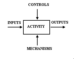
The term "ICOM" is the acronym for the four possible roles relative to a process:
- Input - data or material used to produce the output of a process.
- Control - data that constrain a process. Controls regulate the transformation of inputs into outputs.
- Output - data or materials produced by or resulting from the process.
- Mechanism - people, machines, or existing systems that perform functions or provide energy to the process.
 The particular role of an ICOM is identified by the position of its arrow in relation to the process box, proceeding clockwise around the four sides of the process box. Refer to the representation of a process illustrated in Figure 3-1.
Figure 3-1 ICOM Example
3.1.4 Context Diagram
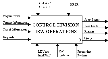
A Context Diagram is a single process and its associated ICOMs. It is always prepared for the top-most process, but it can also be prepared for any other process. The number of a context diagram is the same as that of the process it shows. Figure 3-2, next page, is an example of a Context Diagram.

Figure 3-2 Sample Context Diagram
3.1.5 Node Tree
A Node Tree is a diagram illustrating the hierarchy of related activities. The root or top node of the tree is the context process and its component activities are listed below. A line connects the context process with its component ones. The component activities are further decomposed into their components. Each node consists of the name of the process it represents and a label consisting of a letter followed by one or more numerals. A Node Tree Diagram is a convenient table of contents to the Decompo
sition Diagrams. Figure 3-3, next page, is an illustration of a Node Tree.
 |
| PLAN and DIRECT INELLIGENCE |
CONDUCT INTELLIGENCE OPERATIONS |
ANALYZE AREA of OPERATIONS |
| PLAN and DIRECT ELECTRONIC ATTACK |
CONDUCT ELECTRONIC ATTACK |
EVALUATE THREAT INFORMATION |
| PLAN and DIRECT COUNTERINTELLIGENCE |
CONDUCT COUNTERINTELLIGENCE |
CONDUCT COUNTERINTELLIGENCE |
|
|
DISSEMINATE INTELLIGENCE |
Figure 3-3 Sample Node Tree
3.1.6 Decomposition Diagram
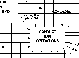
A Decomposition Diagram describes the details of a process. In the decomposition process, a process is decomposed by determining the component activities it comprises. Figure 3-4, next page, is an example of a Decomposition Diagram.
 Click here for full color view of sample decomposition Diagram (234K)
Figure 3-4 Sample Decomposition Diagram
3.1.7 Definitions
The definitions of the activities and ICOMs that appear on the Process Diagrams are provided. These are definitions that have been utilized in building the process model. Developing the glossary also provides the model builders with a good cross-check to ensure that all activities and ICOMs are appropriately identified and clearly defined.
3.1.8 Narrative Text
This is the English language version of the pictorial diagram or view. It is narrative textual information that uses declarative statements to describe what is happening in each process box in the diagram, including interaction between activities. It includes the object of each process and a description of the tasks (decomposition) that are performed to complete the process. Often there is also included a statement that discusses the scope, objectives, and viewpoint of the process model.
3.1.9 Conclusion
This guide should present a framework of understanding for reading the IEW Process Model.
The IDEF0 process modeling technique is a simple but rigorous technique that facilitates communication about how an organization functions in either its current or proposed future environment. The diagrams can be understood easily by both business professionals and data processing professionals and can be used to discuss complex processes.
The IDEF0 process modeling technique provides an opportunity for involvement and consensus among diverse members of an organization as they define a common view of their environment and a strategy for integration.
3.2 IEW PROCESS MODEL
The first step in the production of the process model was to assemble a small analytical team of individuals with extensive experience in IEW and analysis. After the team was assembled, the next step consisted of identifying and acquiring the necessary reference material. The initial references used to provide the framework upon which to build the IEW Process Model were the TRADOC Blueprint of the Battlefield (TRADOC Pam 11-9) and FM 34-1, Intelligence and Electronic Warfare Operations. The third step i
n the process consisted of developing a skeleton model. As the modeling process proceeded to lower decompositional levels, it became necessary to use an extensive library of field manuals, concept papers, and interviews with subject matter experts (SME) who were able to explain in detail how the functions of IEW are performed.
Early in the process, it was determined that the Blueprint of the Battlefield was limited in its description of several aspects of IEW operations. Inadequately addressed were such areas as IEW synchronization, multisensor cross cueing, continuously updated common threat picture, multi-echelon intelligence system of systems support, force protection missions of operations security and counterintelligence (CI), indications and warning, and the close relationship between intelligence and electronic attack
. Similarly, published doctrinal sources were supplemented with SME interpretations of how IEW functions will be performed with the fielding of new systems and the implementation of evolving concepts.
Model continuity across echelons was achieved by expressing IEW functions using the familiar intelligence cycle (direct, collect, produce, and disseminate intelligence). The A0 level was decomposed into three broad processes:
- Plan and Direct IEW Operations. Processes described in this area include planning, requirements management, mission management, resource allocation, and coordination of efforts to accomplish intelligence, electronic attack, and counterintelligence operations.
- Conduct IEW Operations. Processes described in this area pertain to the actual conduct of IEW operations to collect intelligence by the different disciplines, conduct electronic attack operations, and conduct the various types of counterintelligence tasks.
- Produce and Disseminate Intelligence. Processes described in this area dealt with activities and information flows needed to evaluate incoming information, maintain databases and threat situation displays, integrate information, produce intelligence reports, and disseminate intelligence products needed to support the commanders' decision processes.
Appropriate doctrinal publications, beginning with FM 34-1 and its implementing manuals were reviewed with careful attention given to understanding the IEW functions and information flows. Research materials were gathered to include FM and other doctrinal publications. Emerging concepts, such as the MI Branch Concept and explanatory briefings were studied to understand their effects on established doctrine. The goal was to develop a process model that is doctrine-based, but reflects the changes expected
by new concepts, systems, and technological advancements.
Considering the complexity of the IEW process, model reviews by SME throughout the project were essential in providing the most current information possible about the way IEW functions are performed. At each stage of development, modifications to the model were made to reflect the added knowledge gained through SME reviews. These changes were discussed with project sponsors and SME to ensure they reflected the intent of the overall model and the detailed knowledge of the SME.
A complete copy of the IEW Process Model, from EAC down through Direct Support Company at Divisonal Maneuver Brigade, is included in Appendixes A.
 Previous Section
|
Next Section
 The particular role of an ICOM is identified by the position of its arrow in relation to the process box, proceeding clockwise around the four sides of the process box. Refer to the representation of a process illustrated in Figure 3-1.


 Previous Section
|
Next Section