FAS | Intelligence | IMINT | Corona | SU-Space ||| Index | Search | Join FAS


THE SOVIET G-1-e MANNED LUNAR LANDING PROGRAMME BOOSTER*
CHARLES P. VICK, Gaithersburg, Maryland, USA.Journal of the British Interplanetary Society, Vol. 38, pp. 11-18, 1985.
(Presented at the BIS Soviet Technical Forum on 3 June 1983.)
This paper provides a review of some aspects of the Soviet G-1-e booster and its launch complex, including a possible manned lunar mission that they would support and the probable location of the launch facilities.
1. INTRODUCTION
For many years, the most nebulous part of the Soviet space programme has been the development of a manned lunar landing effort and the launch vehicles to support this mission. In the late 1960's there were reports that a booster in the same payload class as the Apollo/Saturn 5 vehicle was being readied for flight, but no successful mission was launched. In the early 1970's reports of launch failures of the giant booster filtered out to the West, with three failures tentatively identified.
In 1974 Spaceflight published [1] an initial analysis of the giant booster programme, the vehicle being called the G-l and G-1-e for Earth orbital and lunar missions respectively, using the late Dr. C. S. Sheldon's classification system. Since then, much more information has been obtained dealing with the giant launch vehicle and its intended lunar programme. This is reflected in the present analysis.
2. THE MANNED LUNAR MISSION PROFILE
Before a rational reconstruction of the Soviet manned lunar booster can proceed, one needs to establish a number of
basic requirements:
-
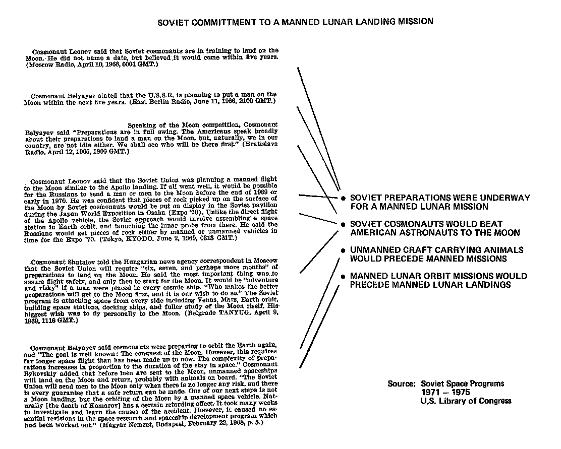
1. That there was a Soviet committment to conduct a manned lunar exploration programme.
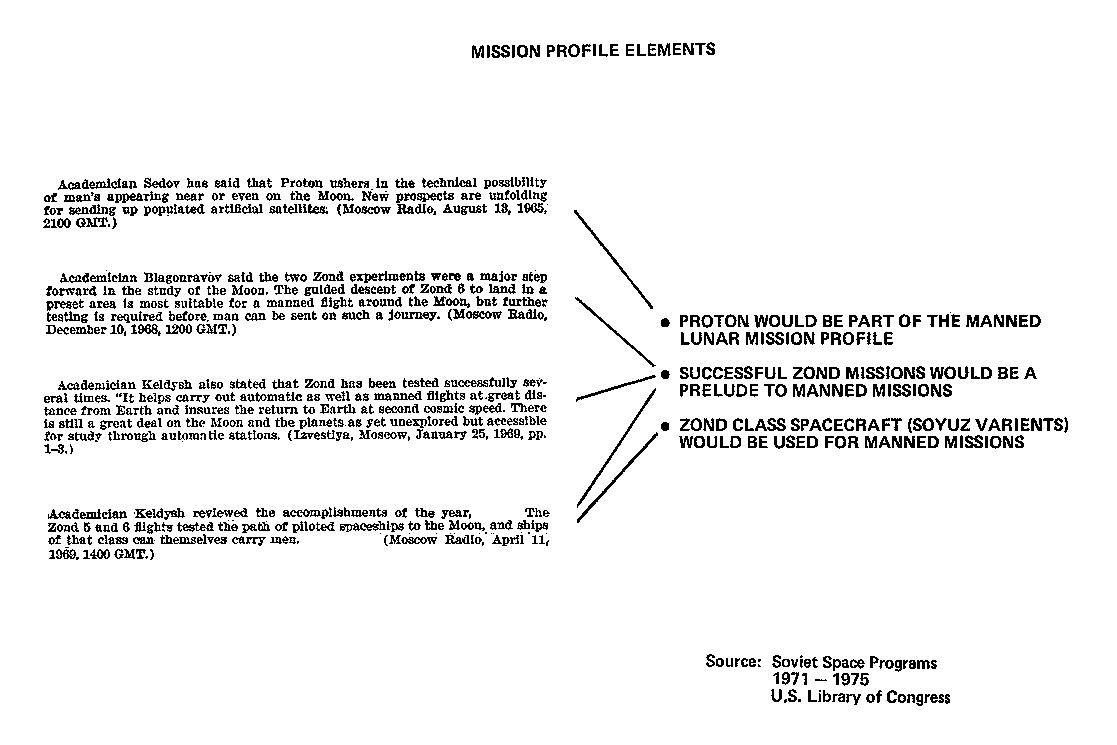
2. That the mission profile is known.
3. That key spacecraft elements of the mission profile are known.
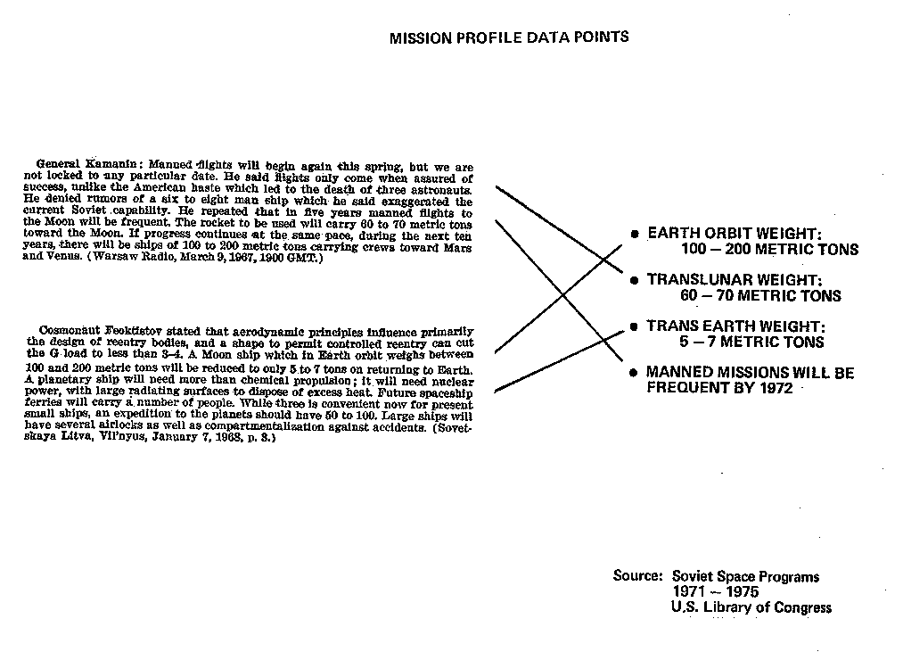
4. That mission profile weight data points are available for analysis.
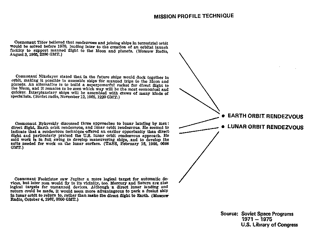
To justify knowledge of the above, four "Quotation Boxes" have been prepared which bring together Soviet quotes from the period during which the lunar programme was developing, together with the deductions that can be made from them. The data obtained from these sources provide the starting point for the mission analysis which follows.
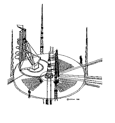
Fig. 1. General view of the Type-G booster launch complex and associated structures.
3. LAUNCH VEHICLES IN THE MANNED LUNAR PROGRAMME
Since it is clear that Earth orbit rendezvous appears to have been part of the mission profile, at least two launch vehicles would have been used for each Lunar mission. Obviously, the G-1-e booster would have been one of these vehicles, since it has always been discussed in terms of this programme and, although the vehicle would be capable of use in a space station programme, such use alone could not justify the vehicle's development.
The Proton D-1 booster was to be the other vehicle since it would carry the fully loaded manned craft that would return the crew to Earth. The A-2 booster would not have the capacity for such a mission.
Possible tests in the programme for a lunar landing came when, on two occasions, pairs of Cosmos satellites were docked in orbit (Cosmos 186/188 and Cosmos 212/213). A similar manned Soyuz docking was accomplished in 1969 (Soyuz 4/5). On these three missions the active vehicle was launched first, followed by the passive target. This is the profile that would have been required if a manned ferry had to dock with a G-vehicle lunar landing complex before the giant booster's upper stage fuel became unusable. During all but the last of the G-1-e test launches there was a double Proton booster countdown.
Although on several occasions there were unmanned heavy Soyuz-Proton type double counts during 1968-1969 and 1971, only during the 3 and 4 July, 1969 double count was there any actual manned crew involved. They were present at the Cosmodrome during the first week of July 1969, for what was presumably intended to be a high Earth orbital Apollo-E type mission. Indications are that this crew was composed of A. Filipchenko, V. Kubasov and a third man, presumably G. Shonin, apparently involved in the heavy Soyuz-Proton part of the mission. Type-G was launched first and failed soon after liftoff, collapsing back onto the launch platform facility. The manned Soyuz-Proton launch was cancelled [2,3].
4. ASSUMPTIONS FOR A SOVIET MANNED
LUNAR MISSION
In addition to the data from the various quotations already noted, a few assumptions have to be made about the payloads and mission profile before further analysis. These assumptions can be classified as relating to either the Proton or Type-G vehicle payload.
4.1 The Proton D-l Payload
It will be assumed that the manned return craft would be a heavy Soyuz, a Soyuz variant fully instrumented and with the full propellant load in its base torus tank. The initial weight would be about 9 tonnes. The crew would be launched into Earth orbit to wait for the G-1-e launch. In addition to the heavy Soyuz, the Proton vehicle could carry an in-orbit propulsion module and/or a life support module or overall mission support module so that the cosmonauts would not have to rely on the limited provisions of the basic heavy Soyuz. After a successful G-1-e launch, the heavy Soyuz would perform Earth orbit rendezvous and then cast off any extra modules before docking. At the end of the lunar mission, the heavy Soyuz propulsion system would be used to perform the trans-Earth injection manoeuver.
4.2 The G-1-e Payload
As noted above, the heavy Soyuz would dock with the G-1-e manned lunar complex in Earth orbit. The G-1-e booster would carry the lunar orbit insertion stage, the Soviet lunar module and a mission support module. The following data have been assumed for the G-1-e payload:
Mission Support Module (MSM) - weight about 2 tonnes; to provide support functions during the trans-lunar and lunar orbit phases of the mission.
Soviet Lunar Module (SLM) - weight about 19 tonnes; this could carry two men to the lunar surface.
Lunar Braking Module (IBM) - dry weight about 2 tonnes; this may be used on the Proton booster's escape stage, and would be used for lunar orbit insertion and orbit trim.
Figure 2 provides a summary of the manned lunar mission as envisaged in this paper.
5. THE G-1-e BOOSTER CHARACTERISTICS:
ASSUMPTIONS
It has been assumed that the G-1-e booster uses three stages to attain Earth orbit and trans-lunar injection. The payload for the vehicle would be the three elements noted in section 4.2, together with the 3-manned heavy Soyuz which would be added in Earth orbit. The velocity requirements for the mission are 9500 m/s [7800 m/s plus losses] for Earth orbital insertion, plus a further 3100 m/s trans-lunar injection, making a total of 12600 m/s. This velocity requirement will be distributed evenly between the three stages of the booster. In addition, the LBM would be required to perform lunar orbit injection, about 1000 m/s.
The structure ratios for the three stages (structure mass/propellant mass) are taken to be 0.070, 0.085 and 0.100; these are similar to those found on the Saturn 5. Specific impulses of 330 sec as an average value are assumed for each of the three booster stages (using lox/kerosene), while the LBM specific impulse is taken to be 290 sec or higher to 307 sec (storable propellant). A 4 tonne aerodynamic payload shroud is taken to be jettisoned with the first stage of the booster.
While the numbers given above are not expected to be exact, they are conservative and reasonable values sufficient to develop an order of magnitude (G-I-e) typical mass schedule.
6. THE G-1-e DESIGN - THE "KOSMODROM" DATA
The Soviet Union has not published a picture of the G-1-e booster although the Kosmodrom book [4] includes some information which seems to relate to the giant booster's programme. A line drawing is presented in the book of a turning tower gantry and, if one follows the contours of the service levels, the design of the booster to match the gantry can be obtained. The result is a vehicle with a conical firststage and standard cylindrical upper stages. The actual number of conical and cylindrical stages cannot be directly determined but the access levels suggest there is a single conical stage and two upper cylindrical stages.
The turning type tower used for the Type-G booster is shown in Fig. 3. The narrative in Kosmodrom indicates:
- "The service turning towers are used for the same purposes as the service trusses, and they can be both moveable and stationary..."
- "The mobile (moveable) towers are capable of being moved on railroad paths (up to 30 m wide) to a distance which ensures their safety during a launch or during an emergency with the RKS (rocket system)."
- "The turning towers are used to service the RKS (rocket system) in one plane. Before launching, these towers are rotated along a circular rail around the central support at an angle which provides for their safety..."
- "The stationary service tower is an autonomous unit with an electrical generator power plant, an air conditioning system, ventilation, lighting network, heating and communications. Its height reaches 100 m, and they weigh up to 3,500 tonnes. Mounted on the service towers are electrical, pneumatic, loading (fill) and drain lines (pipes) with expansion filling connections and as well as a thermostatic, communications system lines are laid on the service towers..."
- "The service cable towers (Masts) and cable masts are used to bring the electrical, fill, drainage and pneumatic lines to the rocket systems. They have different dimensions (height to 100 m. and weight to several hundred tonnes) and they can be stationary or removable (withdrawable)."
- "The stationary towers are mounted on launch system or beside it; such towers have trusses (Platforms) which are withdrawn to a safe distance before or at the time of launch [4]."
Of course, the turning tower gantry illustrated [Fig. 3] provides an indirect indication of the size of the G-1-e. Gantry service levels probably correspond to inter-tank areas, engine bays and service areas. It is interesting to note there is a crane atop the turning gantry which suggests that the booster last stage and payload were stacked using a method operated in the United States for a number of its boosters. The assembled first and second stages are transported to the pad and erected, with the upper stage and payload being lifted atop the lower stage(s) using the crane. The crane also helped to define the centre line of the booster.
7. PUTTING NUMBERS INTO THE G-1-e DESIGN
Knowing the overall design of the G-1-e booster from the Kosmodrom line drawing and with the assumptions noted in section 5, a design study can begin in earnest. Kosmodrom discussed carriers or transporters for booster stages. It stated that the largest carrier must be capable of carrying a weight of 230 tonnes. It is assumed that this refers to the dry weight of some of the part of the G-1-e booster as it is transported to the pad.
Using the assumptions outlined already, a mass schedule for the three-stage G-1-e booster was obtained after many iterations of a computer analysis using the basic equations shown in Fig. 5. The results are noted in Table 1. Four comments on the resulting figures:
-
1. The Earth orbit weight of 151.32 tonnes at insertion and 160.32 tonnes at the beginning of trans-lunar injection agree with the Soviet statement indicating a figure within the 100-200 tonnes or (150 tonnes) range.
2. The trans-lunar weight of 61.51 tonnes is inagreement with the Soviet 60-70 tonne or (60 tonnes) statement.
3. The first stage weight of 231 tonnes agrees with the 230 tonnes figure quoted in Kosmodrom.
4. The launch mass of 4,545 tonnes by convention would seem to indicate a launch thrust on the order of 5,500 to 6,000 tonnes.
Fig. 5. Basic equations and techniques for sizing the G-1-e booster.

TABLE 1. G-1-e Mass Schedule and Propellant Volumes.


7.1 Propellant Volumes
It is assumed that the three main stages of the G-1-e booster use a mixture of liquid oxygen and kerosene. The oxidizer/fuel ratios for these propellants are 2.30 by weight and 1.63 by volume. The bulk density is 1.00 g/cm3, which is equivalent to 1.00 tonnes/m3. Therefore, by volume the liquid oxygen will account for 62% of the load (= 1.63/2.63) while the kerosene will be 38% of the propellant (1.00/2.63). The resultant figures are shown in Table 1.
7.2 The Rocket Stages
The computer analyses undertaken allowed further data to be obtained about the three stages of the booster.
7.2.1 The First Stage
The first stage is a tapered cylinder, with maximum and minimum diameters of 16.0 m and 8.0 m, respectively, giving the best fit. Unlike the upper stages, the LOX tank was below the kerosene tank. Alternative vehicle designs with a storable propellant first stage yielded very poor correspondences with the design constraints. As well as being guided by the Kosmodrom line drawing this reconstruction took into account numerous reports over the years, such as in Ref. 5. The validity of the tapering first stage was confirmed by an illustration in 1980 in Ref. 6. A drawing of the G-1-e first stage is shown in Fig. 4.
7.2.2 The Second Stage
This is illustrated in Fig. 4 and is a standard cylindrical stage. The maximum body diameter of 8.0 m is set by the 50 m level access distance from the gantry hoist centreline. A cylindrical shape and common bulkhead separating the two tanks provided the best fit.
7.2.3 The Third Stage
The final stage of the G-1-e booster would carry a 2 tonne mission support module, a 19 tonne Soviet lunar module and a lunar breaking module for lunar orbital insertion. The third stage performs the initial Earth orbital injection and after docking with the manned heavy Soyuz ferry - the trans-lunar injection (acting as did the S-4B stage on the Saturn 5 booster). A diameter of 4.15 m - thus matching the diameters of the Proton booster payloads - provided the best tank configuration. The third stage is illustrated in Fig.4.
8. THE HISTORY OF THE TYPE-G BOOSTER
In this section the history of the G-1-e booster is chronicled, from its initial concept at the beginning of 1961 to the final cancellation of the programme in its original form in the mid-1970's. It was perhaps at the time of the cancellation that the design studies began in earnest for a second generation Type-L heavy lift launch vehicle (rumours of this began) in 1979 which would be used for the giant spacestation planned for the 1980's. A study of the new booster falls outside the scope of the present paper.
By its very nature, the history of the booster is connected with the story of the manned lunar programme and, therefore, references will be made in the following chronology to events which do not directly involve the Type-G.
1961 Start of the design studies, leading to the Type-G vehicle.
1962 August ? Completion of the initial phase "A" design study. Launch vehicle engine design parameters are defined in this period.
1963 Spring to October ? The design study is completed, setting the final configuration, so that R & D work could begin. The launch vehicle's engine development is started. At this point, the lunar race is "on," with the first test flight set for the spring of 1967.
1964 Early in 1964 facility construction was started on the launch site. Entirely new factory R&D facilities on sitewere required for this programme. The two-bay horizontal assembly buildings' steel structures were being erected and the causeway railway was being laid by the autumn of the year.
1965 The factory facilities were completed and test article construction was started.
1966 Proton 3A suffers an untimely failure during the first quarter of the year. Between the spring and autumn of 1966 the Type-G assembly and launch facilities are nearing completion. The initial ground test articles begin R&D testing. It is during this testing that the first major design flaws of the programme are revealed.
1967 Early in the spring the launch and assembly facilities are completed. Possibly Cosmos 146 was a launch of a heavy Soyuz on a Proton D-l, or D-l-e and was successful. The facilities test vehicle is sent to the launch pad by late spring but the vehicle is not ready for a test flight. The first test flight of the Type-G was then not expected until the early spring of 1968. When did the Soviets actually flight test the heavy Soyuz-Proton?
1968 The Zond D-1-e programme was already a year behind schedule, as was the Type-G. The G-vehicle's April test flight attempt may have been cancelled. The flight test was scrubbed indefinitely, due to first stage engine integration plumbing problems. Was a Type-G launch planned in April 1968? It is certain that a Proton was launched but it failed to reach orbit on 22 April, 1968 due to a second stage failure. Whether it was an unmanned heavy Soyuz or Zond or a first attempted Proton 4 type launch failure is uncertain but its launch time does not match the Zond 4 or Zond 5-8 series window. It does, however, very closely match the automatic sample return window (ASR). It is unlikely to have been an ASR due to the timing gap and the lack of follow-on missions. The Type-G booster's problems were later overcome to the Soviet's satisfaction. Late in the year the Type-G booster enters its final stages of ground testing prior to going to the launch pad the following spring. A manned Zond attempt to circumnavigate the Moon in December is scrapped.
1969 In the late spring the first Type-G flight booster went to the launch pad for a second time. The vehicle was finally launched on its maiden flight to high Earth orbit, 4 July, but it never cleared its towers and collapsed back onto the launch pad, destroying that facility and damaging the nearby second facility. The double count heavy Soyuz-Proton launch with its manned crew (presumably Filipchenko, Shonin and Kubasov) was scrubbed indefinitely. In any case it was not a fuelling operation failure. There was a Type-Gupper stage fuelling test failure during static tests in the autumn. In October the Soviets dropped lunar plans for the time being but continued to work on the launch vehicle problems. A Soviet lunar module flight failed to reach orbit in November.
1970 Initial R&D started in 1967 on high energy fuel engines, and different combinations were tried. By mid 1970's the programme dropped all work but that for the hydrogen/oxygen programme. Cosmos 379, an A-2 launched lunar module ascent stage was test flown in a stripped down form. Cosmos 382, a D-1 payload, was the first full flight test of the lunar module.
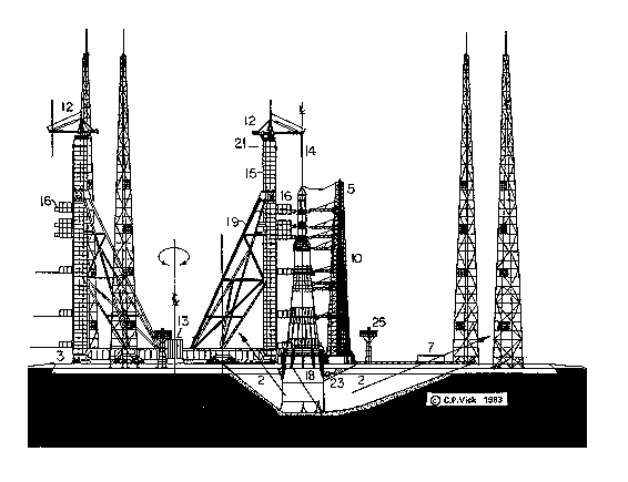
Fig. 6. Side view of the Type-G booster launch complex, showing the four lightning towers, static service tower and rotating service tower both in its stored and operational positions. Beneath the G-1-e booster are three flame deflectors.
1971 Cosmos 398, launched by the A-2 booster, was a test of the lunar module ascent stage with a mission support module. The second Type-G booster was flight-tested on 24/25 June but failed to reach orbit: the vehicle first stage broke up at an altitude of 12 km, destroying the vehicle. The vehicle's break-up was due to instrumentation and engine failure. Presumably, there was a dual countdown of a D-l heavy Soyuz with the second Type-G booster, but the Proton unmanned launch was scrubbed. Cosmos 434 was a further A-2 test flight of the lunar module ascent stage.
1972 On 24 November the third Type-G booster was launched but failed to reach orbit; it was destroyed at an altitude of 40 km again because of instrumentation and engine failure. The manned lunar landing goal had now slipped by three years and was finally cancelled.
1973 The Type-G programme was partially mothballed, with no established programme goals.
1974 The Soviets continue basic engineering ground testing and technical development related to parts of the Type-G programme for possible future use. The prime studies presumably centred on instrumentation, engine R&D, plumbing and vehicle stack dynamic testing.
1975 The destroyed Type-G launch facility was rebuilt. A redesign effort began on the programme, with considerations towards future uses of an improved Type "L" vehicle.
9. THE G-1-e BOOSTER LAUNCH FACILITY
This section can be divided into two: one will look at the design of the Type-G booster launch complex and the other at the probable location of the launch complex.
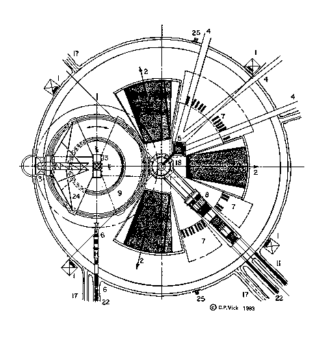
Fig. 7. Plan of the Type-G launch pad, with the combined first and second stages of the booster approaching on one rail line, while the third stage and payload are approaching from another angle.
9.1 The Launch Facility Design
The Soviet book Kosmodrom provides both an illustration and supporting text dealing with the booster service gantry (the turning tower), while there is only text dealing with the umbilical tower. According to Ref. [7], "The pads use service structures that move on large circular rail lines around the vehicle support platform."
Figure 6 is a reconstruction of a side view of one of these launch complexes, while Fig. 7 is a plan of the area. A more general view of the launch complex is provided in Fig. 1.
9.2 Location of the Launch Facility
A number of public sources can be consulted to obtain the probable location of the Type-G launch facility. A US Defense Mapping Agency map of Tyuratam shows that the tallest lightning towers (180 m) are located to the northwest of the original A-booster launch facility. Individual frames from the Soyuz 19 (ASTP) roll-out film show the A-booster assembly buildings on the horizon at the left and a much larger building on the horizon to the right. Finally, Landsat photographs of the area in the last few years clearly show the A-booster complex and what may be the G-booster assembly building, roadways and launch complexes. This old Type-G facility has now been revised to accommodate the new heavy lift Type-L booster.
10. LUNAR COSMONAUT NOTES
O. Makarov was overall Chief Soviet Lunar Module (SLM) Engineer for the Soviet Cosmonaut core while G. Grechko was chief electronics instrumentation engineer for the SLM. V. Sevast'yanov was considered to be one of the prime crewmen for the first outbound manned Lunar mission. In December 1968 only two men went to the Cosmodrome, P.Bel'yayev and his backup V. Bykovskiy, for the Manned Zond circumlunar mission. V. Gorbotka replaced G. Grechko due to influenza just before beginning the Soyuz 7 mission.
Some of the Lunar Cosmonaut Assignments:
FE - Kubasov - Earthorbital (SLM) test flights
FE - Sevast'yanov - Lunar Orbit (SLM) test flight
FE - Makarov - 1st Lunar Landing
FE - Grechko - 2nd Lunar Landing
FE - Rukavishnikov- 3rd Lunar Landing [2]
11. SUMMARY
Despite the lack of official Soviet confirmation, much information can be gleaned from Soviet and non-Soviet sources to allow an overall picture of the original Type-G booster programme to be obtained. From the data presented in this paper it seems that a reasonable G-booster design has been developed and the launch facilities and support building have been located. Rumours of continued work on a giant booster mean that we may yet see its eventual use, although it is uncertain how much the new booster's design may owe to the original Type-G.
ACKNOWLEDGEMENTS
The author wishes to thank the following people for their contributions: Richard Flagg, Sven Grahn, James Oberg, Townesend Reese, Davis Woods, Phillip Clark, Lee Saegesser, Jaques Tizou, Kenneth Gatland, Mme. Kira Caiafa, and the late Dr. Charles S. Sheldon, II.
1. C.P. Vick, "The Soviet Super Boosters - 2" Spaceflight, 16, 94-104 1974.
2. Private conversations conducted with participants in the Soviet Lunar programme.
3. Private communications from Sven Grahn, on 28 July 1969, p.37 and 17 Nov. 1969, p.26, Aviation Week & Space Technology articles relating to tracking and recovery ships deployment for a manned mission in July 1969.
4. A.P. Vol'skiy (ed), Kosmodrom (Voyenizdat Publishing House, Moscow, 1977). Pages 39, 112, 125, 126 and 127.
5. Harry Steine, "The Big Boosters of the USSR," Analog, September 1969, pp.54-73.
6. Aviation Week & Space Technology, 16 June 1980, p. 27.
7. Aviation Week & Space Technology, 9 December 1974, p.9.
8. "ASTP, USSR Groundbase," (Soyuz 19 rollout film) NASA.
FAS | Intelligence | IMINT | Corona | SU-Space ||| Index | Search | Join FAS
http://www.fas.org/irp/imint/85vick_vol38.htm
Created by Charles P. Vick, Sara D. Berman, and
Christina Lindborg, Scoville Fellow
Created by John Pike
Maintained by Webmaster
Updated Tuesday, July 1, 1997