
37 Page 38 39 Appendix C Integrated Architectures Panel
4.1 GENERAL This section describes each of the architecture product types referenced in Section 3. For most of the types, a generic "template" is shown that illustrates the basic format of the product, describes the characteristics to be captured in the product, and lists some of the uses of the product. Additional examples are provided in Annex E. For any architecture effort, the spe-cific products to be produced and the level of detail to which they are developed depends on the purpose of the architecture.
4.2 Operational Architecture Products Standard products associated with operational architectures focus on the warfighting context for C4ISR support, the missions and tasks to be supported, the operational elements involved in accomplishing the tasks, and the information exchanges needed to meet operational needs. Products include:
High- Level Operational Concept Diagrams
Command Relationship Charts
Activity Models
Information Exchange Requirements
Required Capabilities Matrices
Node Connectivity Diagrams The central theme common to these products, as identified in the Integrated Architecture Panel architecture definitions, is the information flow that links operational elements and the activi-ties required to accomplish operational missions. To facilitate applicability across Services, commands, and DoD agencies, the content of operational architecture products is keyed to the warfighting and warfighter support missions and tasks described in the JCS's Universal Joint Task List (UJTL) and task lists derived from the UJTL such as Joint Mission Essential Task Lists (JMETLs) or Service- specific task lists (e. g., Navy Mission Essential Task List [NMETL]).
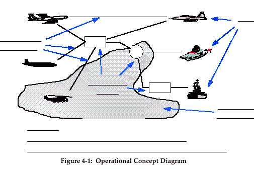
4.2.1 Operational Concept Diagram The Operational Concept Diagram, as depicted in Figure 4- 1 (on the next page), is used to depict the "big picture" view of the operational warfighting context. It is aimed at senior- level decisionmakers and uses a graphical picture to represent a high- level view of the operational
38
38 Page 39 40 Integrated Architectures Panel Appendix C
environment in terms of operational elements or echelons involved, geographic region, nodal
connectivity, types of forces employed, etc.
The figure shows generic icons that can be tailored as needed and used to represent various classes of players in the architecture, e. g., an aircraft icon can represent a particular type of aircraft, or a particular air organization, or the air assets of a joint task force. The icons can also be used to represent missions or functions, e. g., the aircraft icon could represent Air Operations and the ship icon could represent Maritime Operations. The lines connecting the icons can be used to show simple connectivity, or can be annotated to show what information is exchanged. How the template is tailored depends on the scope and intent of the architecture, but in general, an Operational Concept Diagram will show such things as the missions, high- level functions, organizations, and geographical distribution of assets.
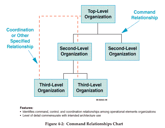
4.2.2 Command Relationships Chart The Command Relationships Chart, as depicted by the template in Figure 4- 2 (on the next page), is used to show the operational elements involved in a particular military operation and the relationships among them. It depicts lines of command and coordination among opera-tional elements and may depict operational elements in either generic terms or by particular organizational element, depending on the particular need. The level of detail to be shown on this chart is commensurate with the intended use of the architecture. This type of chart should be drawn only to the level that depicts the applicable operational elements and lines of com-mand.

39 Page 40 41 Appendix C Integrated Architectures Panel
Command relationships may be important to show in an operational component of an architec-ture
because they illustrate "how business is done." For example, command and control rela-tionships
may differ under different circumstances, such as for various phases of warfare; these
command structures may mean that activities are performed differently or by different units.
Different coordination relationships may mean that connectivity requirements are changed.
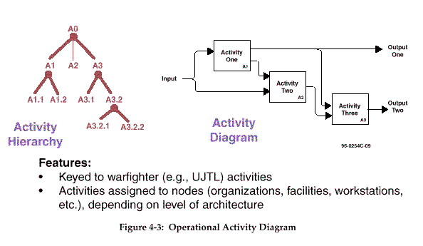
4.2.3 Activity Models As shown in Figure 4- 3 (on the next page), activity models describe the applicable activities associated with specific warfighting tasks that must be accomplished to support a particular mission, the relationship among activities, the data or information exchanged between activi-ties, and the data or information exchanged with other activities that are outside the scope of the model. The models are hierarchical in nature, i. e., they begin with a single box that represents the overall activity and proceed successively to decompose the activity to the level required by the purpose of the architecture.
4.2.3.1 Associated Diagrams. Activity models include two different types of diagrams: the activity hierarchy or "tree" and the activity diagram.
4- 3
40 Page 41 42 Integrated Architectures Panel Appendix C
The activity hierarchy or "tree" shows which tasks are decomposed from others. The hierarchy
of tasks presented in the UJTL represents this kind of relationship. For any given operational
architecture, the activity hierarchy should start using one of the branches of the UJTL as the top
of the tree. The top- level task should be broken down into lower level tasks until the tasks at the
lowest level can be clearly identified with a particular operational element or node responsible
for accomplishing the task. The activity tree should be refined only to the level necessary to
meet the needs of the particular operational architecture being developed. Depending on the
specific objectives to be served by the operational architecture, it may be appropriate for some
branches of the tree to be refined to very low levels whereas others are defined only at high
levels. In many cases, higher level tasks are presented only to show the context within which
the lower level tasks are performed.
The activity diagram shows the relationship among the tasks at any given level of the activity hierarchy. The objective of the activity diagram is to show dependencies among activities, principally with respect to the information flows among them.
Activity models can capture valuable information about an architecture and can promote the necessary common understanding of the domain under examination. However, care must be taken to make sure that the modeling process is performed efficiently and usefully. An ap-proach that CISA has advocated and has used successfully is the template model approach. Using this approach, an activity model template is constructed and used as a guideline for building multiple models that cover the same set of activities but from different viewpoints. The model specifies the activities, generic input/ output/ control/ mechanism categories, and spe-cific characteristics to be captured in the model. The different viewpoints can be those of
4- 4
41
41 Page 42 43 Appendix C Integrated Architectures Panel
multiple organizations that perform similar activities; in that case, the template approach allows
those organizations' processes to be easily compared. With or without the incorporation of
template models, it is often useful to construct a high- level, generic model of the subject in
question and then to build a number of related models of various aspects of that subject area.
The objective in any of these techniques is to focus the modeling effort so that a number of
small, quickly developed models can be used instead of a large, many- layered model.
Activity models generally include a chart of the hierarchy of activities covered in the model, a facing- page text for each diagram to provide any required detail, and a data dictionary that defines all activities and terms used in the diagrams.
4.2.3.2 IDEF0 Modeling Language. IDEF0 * is a frequently used construct for depicting ac-tivity relationships in diagram form. DoDD 8020.1- M, Functional Process Improvement (FPI), was issued as interim guidance in January 1993 and specified the use of IDEF in FPI analysis. IDEF0 can be very useful for providing indepth understanding of functional activities and as such may be considered background analysis in support of operational architecture develop-ment. IDEF0 provides a sound methodology for activity modeling, but it is not the only con-struct that may be used. Other activity modeling conventions, such as DeMarco diagrams, may also be used. The main point to keep in mind is that the purpose of the activity diagram is to depict the relationship among the activities particularly with regard to information inputs and outputs.
The precise structure of IDEF0 activity modeling, especially in view of its widespread accep-tance throughout DoD, imposes a degree of standardization in the diagrams that facilitates common understanding of the presentation of the operational architecture information. A key feature of the IDEF methodology are the accompanying integrated dictionaries that provide precise definitions of activities, their inputs and outputs, the mechanisms that support activities, and the controls that guide how activities should be accomplished. The IDEF methodology also provides a logical progression from IDEF0 activity modeling to IDEF1X data modeling, which is necessary to understand the relationships among the elements of warfighter informa-tion that are the subject of the C4ISR architectures. Data models of warfighter information provide the logical basis for designing and developing information processing systems in sup-port of operational needs. Although not always required, when they are developed, the IDEF1X data models of warfighter information are considered a core architecture product in the Frame-work construct. Additional information on IDEF modeling may be found in DoD 8020.1- M, Functional Process Improvement, January 1993.
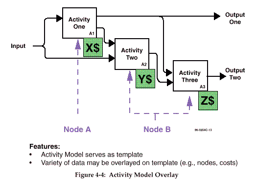
4.2.3.3 Overlays to Activity Models. One way to get the most out of a relatively small activity modeling effort is to overlay additional information onto the basic diagrams in order to gain greater insight without additional decomposition. Nodes that perform an activity can be indi-cated on the appropriate activity box. (This kind of annotation is a standard part of the IDEF0 methodology, and is used in the preceding example. This kind of annotation could also be
* IDEF0 is the activity modeling technique associated with the Integrated Definition (IDEF) language.
4- 5 42
42 Page 43 44 Integrated Architectures Panel Appendix C
added when other methodologies are used.) Costs of performing the activity can be indicated,
and specific attributes of exchanged information can be added to the arrow labels. If such
annotations and overlays are designed carefully, the purposes of the architecture can be fur-thered
with relatively little extra effort. Figure 4- 4 is a template showing some sample over-lays.
The dashed arrows indicate which nodes perform which activities; this information can be used to uncover unnecessary functional redundancy. What constitutes a "node" will depend on the level of the architecture being built and its purpose: in some cases a node will be an organiza-tion, in others a node will be a facility or even an individual workstation. The dollar signs indicate that the costs of performing an activity could be appended as well; this activity- based cost information can be used to make decisions about streamlining, combining, or omitting activities.
4.2.4 Information Exchange Requirements As defined in Section 3, Information Exchange Requirements (IERs) express the relationship across the three basic entities (tasks, operational elements, and information flow) in an opera-tional architecture. Using the defined activities as a basis, IERs identify the elements of warfighter information used in support of a particular activity and between any two activities. IERs iden-tify who exchanges what information with whom, why the information is necessary and in what manner. The information media (i. e., data, voice, and video), quality (i. e., frequency, timeli-ness, and security), and quantity (i. e., volume and speed) are attributes of the information ex-4-
6
43 Page 44 45 Appendix C Integrated Architectures Panel
change that may be included in the IER. Particular capabilities such as automated data pro-cessing
capabilities, secure communications, facsimile, database query, and large- screen dis-play,
may also be captured for each exchange. Required capabilities may be extended to capture
other needs such as personnel skills or facilities. The specific attributes which are used to
describe the information exchange are driven by the purpose for which the architecture is being
developed.
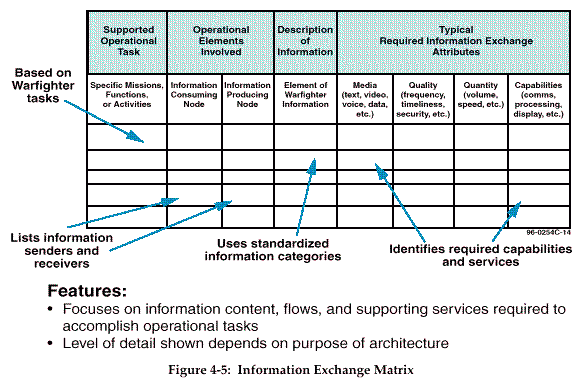
Figure 4- 5 illustrates a matrix approach for representing IERs. The starting point for defining IERs is the activity for which an information exchange is being defined. The activity should be traceable to a specific UJTL task. The matrix is designed to portray each information exchange on its own separate line. Consequently, multiple rows of the matrix may be required to describe all of the information exchanges needed to accomplish any particular activity, and the overall size of the Information Exchange Matrix may become quite voluminous. Fortunately, due to its highly structured format, the Information Exchange Matrix lends itself readily to linkage to relational databases from which the matrix can be generated automatically. In practicality, hard copy versions of this architecture product should be limited to high- level summaries of catego-ries of information exchange or highlighted subsets of particular interest.
As shown in the figure, moving across the matrix, there are separate columns to describe the information that is being exchanged, identify the operational elements or nodes that use and
4- 7
44
44 Page 45 46 Integrated Architectures Panel Appendix C
originate the information, and define the relevant required attributes of the information ex-change
such as the media, quality, quantity, and capabilities associated with the information
exchange.
The scope and purpose of a particular architecture will determine the degree of specificity with which the information and the consuming/ producing nodes are described and the specific at-tributes that are used to describe the IER. For example, for high- level planning architectures, it may only be necessary to identify information exchanges with respect to major categories of information and primary operational nodes involved in the exchange with only a few high- level attributes such as media and security described. To support development of systems architec-tures, however, it will likely be necessary to provide greater specificity as to the information content, consuming/ producing nodes, and media as well as fairly explicit qualitative and quan-titative descriptions of the information exchanges and descriptions of particular types of pro-cessing and communications services that are required.
The elements of information should be described in common terms that can be readily under-stood throughout the C4ISR community. An attempt to develop a standardized list of catego-ries of information is underway as part of refinement of the framework.
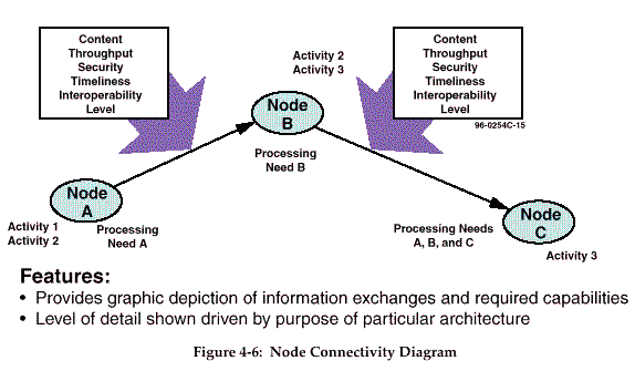
4.2.5 Node Connectivity Diagram Once nodes have been paired with activities , the connectivity required to perform those activi-ties can be illustrated. The Node Connectivity Diagram depicted in Figure 4- 6 presents a visual portrayal of the nodes, activities, and the connectivity required to perform those activi-4-
8
45 Page 46 47 Appendix C Integrated Architectures Panel
ties. The Basic Node Connectivity Model in effect "turns the activity model inside out," focus-ing
on the physical nodes rather than on the abstract activities. The main features of this kind of
diagram are the nodes, the needlines between them, and the characteristics of the information
exchanged. Each IER is represented by an arrow, which is annotated to describe the character-istics
of the data or information, i. e., its substantive content, format (voice, imagery, text and
message format, etc.), throughput requirements, security or classification level, timeliness re-quirement,
and the level of interoperability required for the exchange. The activities associated
with a given IER can be noted alongside the node or on the arrow, in order to allow functional
solutions, rather than systems solutions, to be discovered.
The Node Connectivity Diagram can be used to depict required communications capacities of different types of information (e. g., data, voice, video) between nodes, or particular services (e. g., database access, large screen display) required at different nodes.
The information illustrated in node connectivity models can be used to make decisions about what systems are needed to satisfy the business needs of an organization or functional area. However, it is the business needs that are illustrated, not the systems solutions; therefore, this kind of diagram is included in the operational component rather than in the systems component. No systems have been named yet, except in the very broadest sense, in which a node could be considered a "system."
Except in the case of rather simple situations, any attempt to present the entirety of the required capabilities in Node Connectivity Diagram form will likely detract from its readability and defeat its purpose of facilitating comprehension by the operator or functional advocate for the operational architecture.
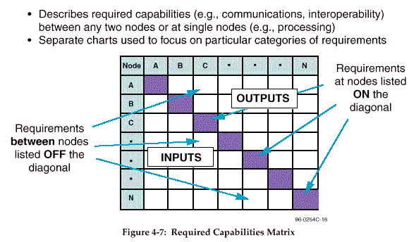
4.2.6 Required Capabilities Matrix The Required Capabilities Matrix, presented in Figure 4- 7 (on the next page), summarizes the capabilities (quantitative and qualitative requirements and services) that are required at a par-ticular node or between any two nodes. As indicated in the figure, the capabilities required at any single node are cataloged in the matrix cells that lie along the diagonal, while required capabilities between cells are cataloged in the off- diagonal cells. The contents of the Required Capabilities matrix may be obtained by summarizing the contents of the information exchange matrices by node.
Normally, the capabilities required between two nodes do not depend on the direction of data exchange. However, occasionally the need exists for documenting "one- way" requirements, such as would be the case for broadcast communications. As can be seen in the template, since there are two cells available for summarizing the required capabilities between any two nodes, the matrix offers the flexibility of cataloging two- way requirements as well as separate one-way requirements in each direction. In particular, since information generally flows into, as well as out of, nodes, the boxes in the lower diagonal can be used to describe information inputs while the upper diagonal can be used to describe outputs.
4- 9 46
46 Page 47 48 Integrated Architectures Panel Appendix C
Because the Required Capabilities Matrix simply represents a summary by node and by node
pair of the information contained in the Information Exchange Matrix, use of a relational data-base
to maintain the contents of the Information Exchange Matrix database would permit easy
rapid generation of the Required Capabilities Matrix. The "input- process- output" format of the
matrix is consistent with activity modeling and provides a convenient way to summarize some
of the information in activity models.
4.3 SYSTEMS ARCHITECTURE PRODUCTS The systems component products are largely derived from the operational component products and are therefore dependent on the operational component products for their focus and level of detail. Warrior ownership of the operational component products provides the driving opera-tional vision, while the C4ISR architect uses the systems architecture products to provide the necessary systems and connectivity support to that vision.
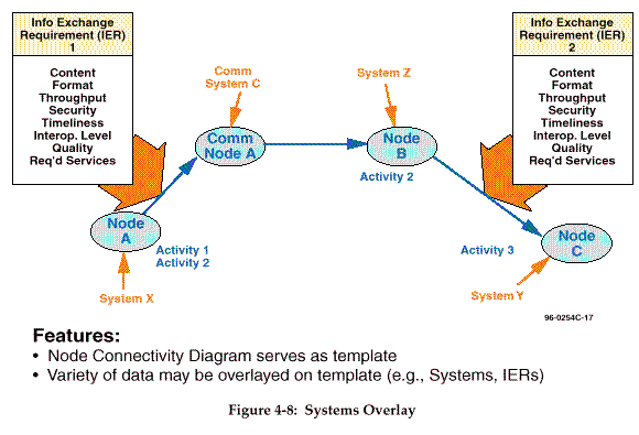
4.3.1 Systems Overlays Systems Overlays assign specific hardware/ software systems to the nodes described in the Ba-sic Node Connectivity Model. These systems assignments are shown as overlays to the Basic Node Connectivity Model. Depending on the focus of the architecture, these systems can in-clude automated information systems, communications systems, or others. In addition, com-munications nodes are depicted, to trace the path of an IER from its source to its ultimate
4- 10
47
47 Page 48 49 Appendix C Integrated Architectures Panel
destination, as are the required services. The systems information captured in these overlays
can be used to compare systems used at various nodes in order to identify opportunities to
improve performance or eliminate redundancies by making system changes.
A template for a Systems Overlay is shown in Figure 4- 8; this is a modification of the template for the Basic Node Connectivity Model.
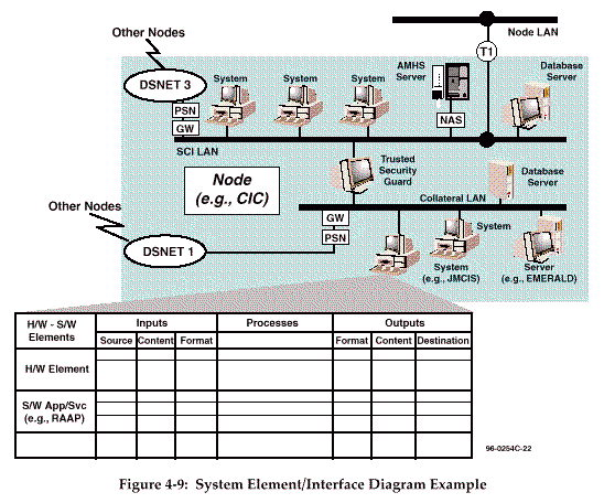
4.3.2 System Element/ Interface Diagram A System Element/ Interface Diagram decomposes the nodes from the Node Connectivity Model with System Overlays to reveal the relationships among the systems resident at the nodes. The systems, their configurations, and their linkages are shown on the diagram. A table is con-structed that shows the relevant data/ information exchanges between systems within the node and the data/ information exchanges between systems at the node and systems at other nodes (external exchanges). For each system, the inputs, processing, and outputs of the system's hardware elements and applications are listed. The detailing of the external exchanges allows an IER to be analyzed to determine which systems at which nodes contribute which data ele-ments of an IER. This kind of information can be used to analyze and improve the configuration of systems and local area networks (LANs); to determine more efficient distribution of soft-ware applications; and, in conjunction with the System Performance Parameters Matrix and
4- 11
48
48 Page 49 50 Integrated Architectures Panel Appendix C
portions of the technical architecture component, to examine interoperability problems. A no-tional
example of a System Element/ Interface Diagram is shown in Figure 4- 9.
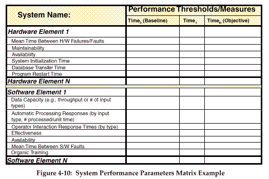
4.3.3 System Performance Parameters The System Performance Parameters Matrix builds on the System Element/ Interface Diagram to describe the current performance characteristics of each system, and the expected or required performance characteristics at specified times in the future. Characteristics are listed sepa-rately for the hardware elements and the software elements. The future performance expecta-tions are geared to the Technology Forecast portion of the technical architecture component. Figure 4- 10 (on the next page) shows an example of a System Performance Parameters Matrix, listing representative performance characteristics.
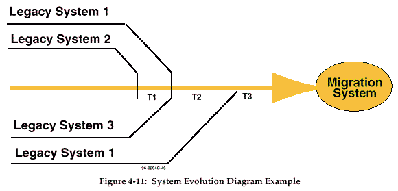
4.3.4 System Evolution Diagram The System Evolution Diagram describes plans for evolving a suite of systems into a more streamlined, efficient (smaller and cheaper) set. It builds on the previous diagrams and analy-4-
12
49
49 Page 50 51 Appendix C Integrated Architectures Panel
ses in that information requirements, performance parameters, and technology forecasts must
be accommodated. An example System Evolution Diagram is shown in Figure 4- 11.
4.4 TECHNICAL ARCHITECTURE PRODUCTS As defined earlier, the technical architecture provides the technical guidance that governs sys-tem implementation and operation. There are a number of technical reference models (TRMs) in existence that can serve as sources for technical guidelines, such as the DoD Technical Archi-4-
13
50
50 Page 51 52 Integrated Architectures Panel Appendix C
tecture Framework for Information Management (TAFIM), the Joint Technical Architecture
and the Army Technical Architecture. In addition, some descriptions of information standards
are available, such as the Defense Data Repository system (DDRS) and the C2 Core Data Model.
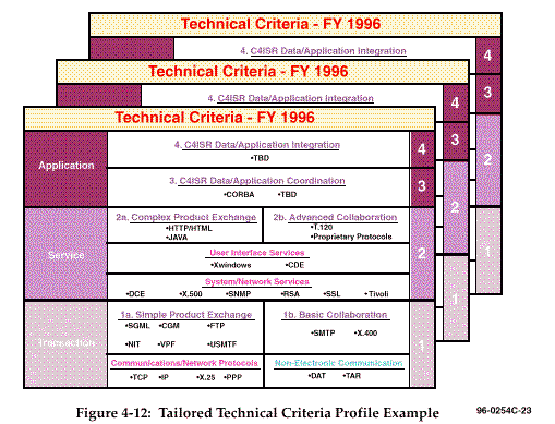
4.4.1 Tailored Technical Criteria Profile In many cases, especially in building architectures with less than a Service- wide scope, "build-ing" a technical architecture will really consist of identifying the applicable portions of existing technical guidance documentation, tailoring them as needed, and filling in any gaps. The Tai-lored Technical Criteria Profile is a product that helps to capture the technical guidelines appli-cable to a given architecture. The profile is time- phased to facilitate a structured, disciplined process of system development and evolution. Time- phasing also promotes the consideration of emerging technologies and the likelihood of current technologies and standards becoming obsolete.
A Tailored Technical Criteria Profile constructed for a given architecture will be structured as appropriate in accordance with the purpose for which the architecture is being built. For ex-ample, an architecture may be built to examine issues of information system interoperability. In that case, the Tailored Technical Criteria Profile could be organized around the applicable levels of interoperability. The Tailored Technical Criteria Profile would show the enabling functions and criteria for each of the required levels of interoperability. An example of such a Tailored Technical Criteria Profile is shown in Figure 4- 12. (Levels of Interoperability are discussed in Section 4.6. Levels shown here are for illustration only.)
4- 14
51
51 Page 52 53 Appendix C Integrated Architectures Panel
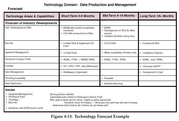
4.4.2 Technology Forecast
A Technology Forecast is a detailed description of emerging technologies and specific hard-ware
and software products. It contains predictions about the availability of emerging capabili-ties
and industry trends in the 6- month, 12- month, and 18- month time frames, and confidence
factors for the predictions. The forecast includes potential technology impacts on current archi-tectures,
and thus influences the development of transition and objective architectures. The
forecast should be tailored to focus on technology areas that are related to the purpose for which
a given architecture is being built, and should identify issues that will affect the architecture.
Figure 4- 13 depicts a sample Technology Forecast focused on the area of data production and
management.
4.5 CORE INFORMATION PRODUCTS The data model and data dictionary are considered core products because they relate to all three types of architectures. There are two types of data sets associated with architectures: architec-ture information and warfighter information.
Architecture information are the things that are described in architectures. These include all those terms associated with the three types of architectures such as missions, tasks, operational elements, nodes, systems, services, and standards. Annex A contains an initial version of a
4- 15
52
52 Page 53 54 Integrated Architectures Panel Appendix C
entity- relationship (E- R) data model for architecture information. The Annex A example fo-cuses
primarily on information associated with operational architectures but the approach is
applicable to all three architecture types.
Warfighter information is that data required by the warfighter to accomplish tasks. It is that data to which the IER refers in the operational architecture, the data which are being passed between systems in the systems architecture, and the data for which data element standards are defined in the technical architecture. A strawman taxonomy of warfighter data is provided in Annex D.
4.5.1 Data Model
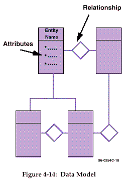 The data model describes the data and the relationship between data elements. A common approach
is to describe the data in terms of entities and relationships. Entities are objects that exist and are
distinguishable from other objects. A relationship is an association among entities.
Data models may be developed for architecture information and for warfighter information. A separate model would be developed for each of these two types of data.
Figure 4- 14 is a template for a data model.
4.5.2 Data Dictionary The data dictionary is a repository of information about data such as definition, relationships to other data, origin, usage, and format. It provides a com-mon reference point for the definition of information, documents information structures, and identifies stan-dard data elements. Data dictionaries may be devel-oped for architecture information and for warfighter information.
In Section 3, the data dictionary is included as an es-sential part of a technical architecture because of the critical role that standard data elements play as part of system standards. Standard data elements are the fundamental interoperability enabling feature of all systems; they are the basis for common interpreta-tion, processing, the display of information, and com-munications efficiency. The data dictionary is considered a core product because of its applicability to operational and systems architectures as well as technical architectures. Data dictionaries of warfighter data are important tools in understanding the information flows within the opera-tional and systems architectures. Data dictionaries of architecture data apply equally to all architecture types.
4- 16
53
53 Page 54 55 Appendix C Integrated Architectures Panel
Data dictionaries are necessary to support the understanding and sharing of information among
different communities, and greatly simplify the development of architecture features. The data
characteristics contained in the dictionary are used to design, monitor, document, protect, con-trol,
and understand the data in an automated system. They support information reuse, resulting
in reduced data duplication, reduced costs, and increased data consistency. Because architec-tural
requirements constantly change, and a change in one part usually affects other parts of the
architecture, a repository also enhances configuration management procedures.
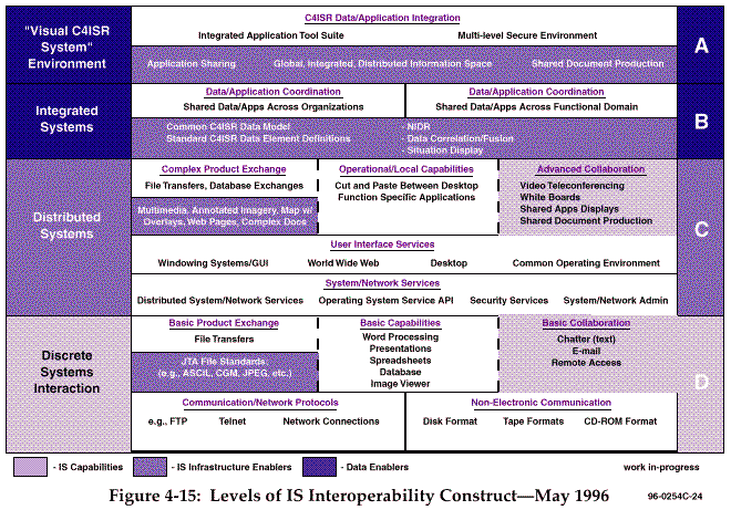
4.6 LEVELS OF INTEROPERABILITY CONCEPT The Integrated Architectures Panel has endorsed the concept of standard descriptions for levels of information system interoperability. The concept is currently a work in- progress. When finalized, the incorporation of the Levels of Interoperability into the architecture development process will better clarify interoperability capabilities and requirements across systems. This concept can be associated with several of the architecture products discussed in this section and can serve as an integrating mechanism among architecture components. The level of node- to-node interoperability required (per IER) is defined during the process of developing the Basic Node Connectivity Model of the operational architecture component. In building the Systems Overlays to the Basic Node Connectivity Model and the System Element/ Interface Diagrams, the node- to- node interoperability requirements are translated into required levels of interoperability between systems. The current version of the levels and their meanings are illus-trated below in Figure 4- 15 (on the next page).
4- 17
96- 0254C- 24 54
54 Page 55 56 Integrated Architectures Panel Appendix C
This Page Intentionally Left Blank
4- 18 55